Hercules 1
Fall 2024 - Current
"Hercules" is the name of the engine that I intend to use as a medium to learn the not-so-basics of propulsion, liquid biprop engine / rocket design, project management, and more. I like to keep myself engaged in projects outside of work and this is the latest one.

Fig. 1. Exploded view of the Hercules Engine. Parts include: Chamber, Jacket, Saddle, Test Cover Plate, Injector Plate Top, and Injector Plate Bottom.
Abstract:
This is a self-directed, fully integrated project engine that involves engineering disciplines including, but not limited to, propulsion, fluids, mechanical, electrical, and software design. "Hercules 1" is a liquid bipropellant engine that I conceptualized with a colleague of mine on 10/30/24. This engine will run on 2-Propanol (C3H8O) and Nitrous Oxide (N2O) and is slated to produce 1100lbf of thrust with a specific impulse of 220s.
If this page has not been updated recently, feel free to skim through our notes. We update this document as we work in real time, so it will be our most up-to-date research on this rocket.
This project was put on pause in August 2025 because I was starting classes at UCSD. I was paying for this project out-of-pocket, so I could not afford more time and money. Since starting UCSD, I joined the Students for the Exploration and Development of Space (SEDS), one of the rocket teams at UCSD.
I joined the team and immediately began developing another regeneratively cooled engine. With my knowledge from Hercules, I was able to dive much deeper into the regenerative cooling design, as well as slim down the design to 2.0 FOS using classwork and Hercules as my knowledge base for FEA. Also, this engine operates with IPA and LOX.
I've had two successful Design Reviews and am now in the fabrication phase with a predicted static fire date in February.
Unfortunately as of now, this project cannot be featured on my portfolio.
This page, Last Updated: 01/09/2026
Project Introduction & Design Philosophy
My experience with aerospace engineering concepts started in my freshman year at BU in 2019 and took me through 2021. I worked on two projects with Boston University Rocket Propulsion Group (BURPG) that taught me a lot but admittedly, I left a lot on the table. Now I'm returning to rockets and engine design with a fresh mind and a matured skillset that will enable me to see a complex, independent project like this all the way through. I called a friend one day to see if he would join me and Hercules was born. I'm excited to exercise concepts I've learned as a professional like project management, test engineering, electrical design, controls, DFM, etc., and implement them into a high-caliber project.
My design philosophy recently has been to "learn by doing" and one of my mantras is "just do something". Hercules is a perfect showcase of both of these because we started this project completely green to these concepts. But, the only direction to go was forward so we dove head-first into this project with nothing but strong fundamentals.
Schedule
Below is a link to our full project schedule (Last updated for portfolio: 11/15/24). This schedule is not perfect This schedule is intended to be semi-malleable, and will solidify as we progress. One of the main tenets of this project is to "have fun", so we will not be extremely rigid with our scheduling - though we do intend to have a engine complete in a sensible amount of time. Another tenet of this project is "actually complete it".

Fig 2. Gantt chart-style schedule. Reference only, currently out-of-date (as of 07/21/25).
Phase 1: General Research & Project Planning
Week 1 started with trying to learn what I don't know. After a week or so of skimming textbooks and watching whatever videos I could find on the basics of propulsion and engine design, I had a semblance of an understanding of liquid biprop rockets and had enough to build a schedule. This would be the foundation of the entire project.
Project Schedule
One big hurdle of this project is that it will be highly asynchronous. My co-founder and I live about 2500 miles away (MA & CA), so we needed to implement a robust project framework to keep up-to-date with each other, stay organized, share files, etc. We meet about once a week, but continue to talk throughout the week in spurts.
Between the kickoff of this project (10/30/24) and our first cold fire makes about 7-8 months. This is an incredibly short time to learn these concepts from scratch while both working a full time jobs, but this is our challenge and successful completion will be a testament to our goalsetting and work-ethic.
Initial System Requirements
The first few things we decided early were:
1) Engine type (solid, hybrid, monoprop, or biprop)
2) Propellant(s)
We took it upon ourselves to push our limits and opted for a liquid biprop rocket using 2-Propanol (C3H8O) and Nitrous Oxide (N2O). Compared to the other types of engines we looked at, this was on the more complex side, but found enough literature to be confident that we were not flying completely blind.
With the groundwork laid out, all that was left to do was to dive straight into liquid biprop engine design and brush up on our high level thermochemistry.
Phase 2: Initial Engine Design & Feasibility
In the spirit of "learning by doing", we started this next phase by diving deep on the propulsion theory. Tools like RPA and NASA CEA were critical here. After learning what rockets were generally possible, we zeroed in on a design that seemed most viable and most productive in terms of learnings gained. Then, we developed a full feasibility plan which included total project cost estimates.
Initial Engine Design
At a high level, engine design feels like throwing darts at a dartboard. But with the help of a few engine design softwares like RPA and NASA CEA, as well as textbooks and papers including, but not limited to, Sutton and Huzel, we were able to build the theoretical foundation of our soon-to-be real rocket engine. Having never done this before, there was a lot of iteration and discussion around what is best practice and what we can design with (and around) to best suit our project's needs.
In the first few weeks of this phase we determined our theoretical thurst force (1100lbf) and our predicted chamber pressure (500psi). We developed a tool that calculates conical engine size based on inputs like Ox, Fuel, L*, thrust, etc. This was soon replaced by RPA's engine contour tool which could more easily calculate bell shapes.
Feasibility
With the groundwork laid out enough, we launched a feasibility study to definitvely "go/no-go" the intial design. This feasibility study covers everything from engine design to test stand design to software & controls. We cover every subsystem and evaluate its engineering feasibility and cost feasibility at a high level. Spoiler alert, the engine design was a "go".
Total predicted cost: $5,000-10,000
Phase 3: Engine Design
This phase encompasses the entire engine design from engine contour, injector design, to regen cooling design, all slated for fabrication in the next phase.
Cooling
With our main propulsion theoreticals set, we could proceed to the more niche propulsion concepts like injector design and cooling methods. We started looking at different methods of engine cooling and ran a quick study on the benefits and detriments of all known types of cooling. We quickly settled on "regenerative" cooling because it was involved and interesting. It was a high-reaching goal, but still achievable. Instead of using welded channels or electroplated channels, we opted for a milled-channel design meaning that these cooling channels would be machined directly into the engine shape, made of C101 (Copper). This is one piece of a "saddle-jacket" cooling design.
Initial CAD, Factor of Safety, & O-Rings
Having settled on the engine cooling type, we could start CAD on the actual size and shape of the engine. We started in RPA using their thermal calculations on channel width and depth, and built our saddles and jackets around this engine contour. The saddle and jackets are not intended to be the main medium for heat transfer, so for strength and cost reasons, they are AL6061-T6. Next, we began to incorporate sealing o-rings into these engine components. Parker's O-Ring Handbook was all we needed to properly design o-ring glands for our uses.
These designs were iterated multiple times and checked with hoop stress calculations to approximate part strength. This brings us to FOS. There was no predetermined FOS for engine components. We read extensively about best practice from NASA handbooks and asked a lot of questions to people who had done this before. Our general consensus was that would we ensure that our rocket would perform, omitting rigid requirements for weight. These parts have a FOS of about 4.0 to protect against shock loads in say, a hardstart, ensuring that we can re-fire if uncharacteristic loads occur. This FOS 4.0 is also partly derivative of the size of this engine. Engines this small (measuring about 5" dia, 8" long) can have thicknesses that are nearly impossible to machine with enough rigidity for handling. Typical FOS for critical propulsion components can be as low as 1.5, but we opted to go safer for our first engine.


Fig 3. Left is front view of the chamber (light blue), saddles (dark blue), and jacket (transparent). Right is an isometric view of the chamber, saddles, and jacket in a section view.
Injector Design
Now with the main chamber complete, we moved onto the injector plate(s). We started with copious amounts of research with Sutton, Huzel, NASA, etc., to determine the most viable injector designs. We settled on an quadlet impinging injector (which nicely fits our 3:1 OF ratio). Again, we looked for a mixed of good performance, a challenging design, and something that was approachable. We spent a lot of time with 3D momentum vectors and developed our own custom tool to iterate through different designs of impinging injectors. This tool can cover different propellants, different ratios of Ox and Fuel orifices, and any number of elements (each Ox and Fuel set of orifices is one element) meaning that this can see use in other projects as well.
Using this tool, we were able to iterate through different 3D designs and settle on the most optimal for our engine's diameter. The orifice plate (brown) is made of 316SSfor high tolerance machining and relative low cost, and the cover plate (green) is made of AL6061-T6 for weight reasons and to further cost reduce this assembly.

Fig 4. Example of impinging flows (ox blue, fuel orange) in 3D CAD based on tool calculations.

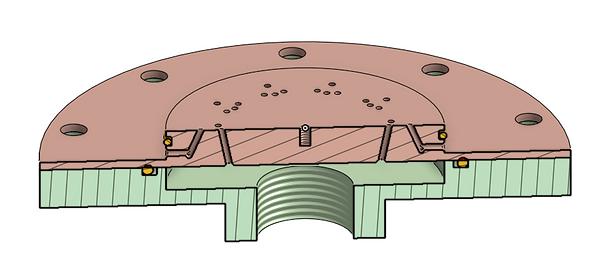
Fig 5. Left is iso section view of the injector plate with orifices. Right is iso section view of the completed assembly including o-rings (green is injector cover plate / oxidizer inlet).
Phase 4: Engine Validation, Engine Fab, Feed System Design, & Test Stand Design
This phase completes the engine design, feed system design, and test stand design. There is a small amount of overlap with feed system / test stand with the electronics, so some considerations here have impacts on the next phase.
Design Validation using ANSYS
Before ordering engine components, we used ANSYS Mechanical to validate the static strength of our parts. After designing with basic hoop stress calculations, used more intensive simulation to further confirm that these parts will not yield under our operating conditions. These designs served as vessels for learning ANSYS, and now, we can iterate through these simulations quite quickly, which came in handy for the test stand design.
All of these simulations passed with flying colors. These parts saw no lower than 2.5 FOS yield (based on their respective materials).
Fig 6. .gif of the injector plate cover under ~600psi, simulating the pressure inside the injector plate trying to escape to atmostphere.
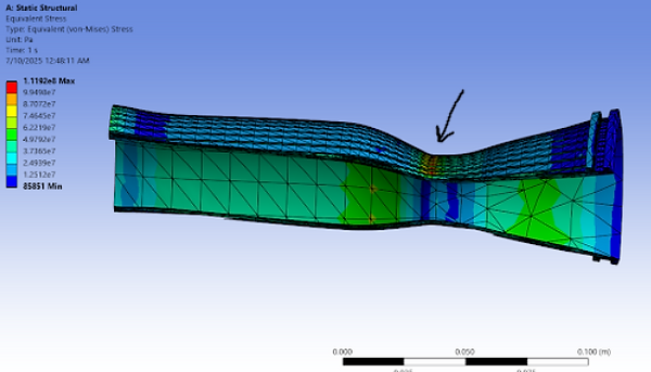
Fig 7. Image of the resultant simulation of ~800psi trying to compress at the end of the nozzle, where the pressure differential will be highest on the chamber. Note the stress riser at the throat.

Fig 8. Image of the resultant simulation of ~800psi trying to expand the jacket to atmospheric pressure.
Engine Fabrication Plan and Assembly Plan
While designing the engine, considerations were made in real time for fabrication and assembly. All CAD had a nominal fit tolerance of 0.005" unless otherwise driven by tighter requirements, for example, the o-ring glands. Early in the program, we envisioned machining these parts using a manual mill, but came to realize that it would be much quicker and more accurate to have these parts done by CNC. A colleague of ours had readily available connections to cheap, quality CNC machining, so we could let loose a little bit and have these parts CNC'd with little worry of simplifying our designs or creating jigs to have some of these more complex contours made. No formal fabrication plan was created due to the low part count and strong communication with the machine house in real-time.
We also prepared an assembly plan to account for all hardware, o-rings, main components, and show how they would come together.
Feed System
As with any new design, we started with high level research. We were able to build a high level P&ID as a starting point for the actual fittings. In order to keep cost down, these fittings are all off-the-shelf, meaning that are number of components may be higher than necessary in custom feed system. This P&ID went through 4 major revisions before we were comfortable with ordering parts. Accompanying the P&ID below is a more detailed version that shows every fitting and adapter.
The most involved part of this design was sourcing the components are attempting to cost-reduce as much as possible. This design features mostly NPT fittings for cost and availability, but also a few AN fittings to add flexible tubing where necessary.
The motorized valves will be controlled via servos, which will factor into the electrical system design.
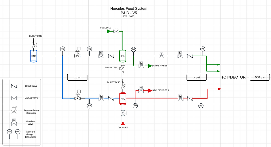
Fig 9. High level P&ID outlining where major components are placed.
Test Stand Design, Overview
Early on, we decided we would be static firing our engine at Friends of Amateur Rocketry (FAR) in Mojave, CA. This amateur test site is renown and happens to only be about a 1.5hr drive away from home. Knowing this, we are able to leverage their existing test stands and relieve ourselves of a good bit of structural engineering. Though, we do still have to interface with their test stand and make sure our engine doesn't go anywhere, so that job wasn't complete yet.

Fig 10. CAD of the test stand with engine, load cell mount, and "angle bracket". Some hardware not pictured.
Before diving into the "angle bracket" design, I want to note that the engine and load cell don't look connected in the image above. We intend for 80/20 rails to take this space, but don't yet know the height required by the Oxidizer inlet tubing (small fitting in that area). We've run the calcs for the buckling load of these railings and have confirmed that these rails will be the absolute last thing to break (~3-6" length).
Test Stand Design, Angle Bracket & Load Cell
To properly measure this rocket's thrust force, we will be using a simple S Load Cell. Other than incorporating this into our electrical system, mounting this load cell is the most critical part of this design. Not only does the load cell need to be mounted properly, it has to be done without failure. The angle bracket is the only thing here keeping the engine from flying away. There is no margin for error here as this is an extreme safety hazard.
We started our search with off-the-shelf components to reduce cost, but quickly realized it was difficult to find angle brackets, shelf brackets, or anything of the sort of ample force rating. Even having run our own simulations on OTS parts, we were unable to find a quote unquote "cheap option". So we opted for a custom design.
We created a 1 part bent sheet metal part, but when we got quotes, the part cost was exubrant because high volume production sheet metal benders could not bend the flange ratio we were looking for. Lower volume shops charged a lot. We edited the part to fit in the cheaper tooling, but the performance was reduced. So we opted for a 3-part construction and went with sendcutsend.com. For mild steel, we're looking at about 40ksi yield or 275MPa (2.75e8 Pa). We're simulating these brackets at 1100lbf.

Fig 11. OTS bracket with pre-casted holes in the wrong spots. We would have to machine our own holes. Additionally, this bracket would yield even at its most ideal.

Fig 12. Tested a bracket design for sanity check (and to play with ANSYS more). Visually, this bracket is clearly going to yield. The simulation confirms this.

Fig 13. 1-part construction. This bracket will not yield, but as a critical structural components, the FOS is quite low (<2).
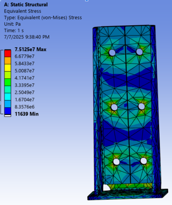
Fig 14. 3-part construction. This bracket will not yield, and the FOS is much better at just below 4.
This 3-part construction was the clear winner because it does not incur a exorbitant amount of cost and gives us a relatively high FOS. Compared to the 1-part construction, it is ~2x stronger and only costs about 40% more.
Phase 5: Electronics & Software
This phase covers all electrical hardware and software. This includes everything from power electronics to the feed system servos and the radio communications between the Test Stand and Launch Box.
Main Requirements
The main objective for this system is to be able to send controls signals to the servos on the feed system as well as receive accurate pressure and thrust data. One safety requirement related to this subsystem is a minimum distance of ~200ft to the launch pad. This requirement presented a challenge to our method of data transmission. I chose to have this system communicate over radio, rather than a long ethernet cable, simply because it would be more of a learning exercise in signals and communications.
The electronics system is comprised of a few components:
- Microcontroller & Radio module
- Servos
- Pressure sensors
- Load cell & ADC
- Power / Battery
Components Selection
The microcontrollerwas selected based on its ease of use and built-in radio capability. We chose a Feather M0 LoRa because its a battery operated board with a LoRa module built in. This board also happened to have enough pins for everything we needed, which saved us from having to buy and use expansion boards.
The servos were selected based on their ability to turn our ball valves with ample torque. We already had the ball valves ordered, so we designed a 3D print (to be used on the actual feed system) that could be modified to accept different motors. We tested multiple motors and found one that consistently met our expectations. We could have measure the torque on the ball valve and compared that with specs from servos online, but we had no accurate way to do that, so we just bought a few servos to test.
The pressure sensors we selected based on their output mode and for their range and accuracy, as well as cost. We chose voltage-based sensors because that was the easiest to handle from a microcontroller and DSP perspective. We chose sensors that had a range up to 1600psi. Our maximum pressure would be 1000psi, only seen in system validation testing, but we needed some overhead to not distort the data as it got towards 1000psi. Our minimum burst pressure for any of our components was rated 1500psi, so if this component bursted, we could see it in our data as well.
The load cell was chosen based on its range and accuracy, as well as its configuration. The load cell is rated up to 2000lbf, in an S-configuration for stability. We could not find readily available load cells closer to our 1100lbf theoretical thrust, so we chose the next best option.
The ADC was chosen for its ease of use and cost. This is a readily available, cheap part that interfaces nicely with our Adafruit Feather M0 and our load cell.
The power components were last to be selected and driven by the operating voltages of everything above. We chose to use a car battery rated for 30A (worst-case system draw), with buck converters to step down from 12V to 5V (servos and sensors) and 3.3V (microcontroller).
Radio Development
This was the most intensive aspect of this subsystem. I had little to no experience with communications, but developed an Rx and Tx script (control center and launch pad) that could send controls signals (i.e., pressurization sequence, abort, launch, etc.) and receive pressure and thrust data.
This involved getting highly familiar with the microcontroller, sensors, and radio to be able to parse the data at the right moments in a noisy environment where there are likely other radio signals around. I implemented CRC8 and simple addressing to ensure the signals coming in and out where the right ones. If the signals were bad or connection was lost completely, the launch pad would abort (servos set at a particular default setting) via a software watchdog timer.
PCB Developement
Due to large amount of electrical components (over a dozen), I chose to create PCBs. With custom boards we can connectorize everything, making assembly / disassembly more efficient, as well as reducing signal noise and size footprint. This resulted in a few board designs:
- Microcontroller Shield
- Pressure sensor board
- Load cell / ADC board
- Servo power and signal boards
I have to say, this was the most enjoyable part of the electrical system. I got to learn new software (KiCAD and EAGLE), and I got to learn what it takes to make a PCB firsthand. As a mechanical engineer it was really easy to take for granted these small boards that go in everything electronic. This also turned out to be a necessary step in development because it forced us to create clean layouts for wiring.
Below is just one of a few board designs I created.
Fig 15. Pressure sensor board, used for connectorizing and powering all the pressure sensors.


Fig 16. Pressure sensor schematic.
Phase 6: Testing
Pre-static-fire Engine Validation
With the engine parts in hand we need to validate that it won't completely explode at the launch pad. I contacted my old place of work, Orange Coast Testing, Inc. for some advice on hydrostatic testing these parts. I designed the parts for 2x or more operating pressure, so we would test at 2x. We designed a cover plate for the nozzle for this very purpose.
Once all the engine parts were validated structurally, we could cold flow at operating pressure.
Once these steps were complete, we could confidently static fire (hot fire) this engine and measure our thrust.
01/06/26 Notes
This project was put on pause in August 2025 because my teammate and I were starting classes at UCSD. Since starting, we joined the Students for the Exploration and Development of Space (SEDS), one of the rocket teams at UCSD.
We joined the team and immediately began developing another regeneratively cooled engine. With our knowledge from Hercules, we were able to dive much deeper into the regenerative cooling design, as well as slim down the design using our classwork and Hercules as our knowledge base for FEA. Also, this engine operates with IPA and LOX.
We've complete that design and are now moving towards fabrication with a predicted static fire date in February.