ME360 Assignment 3:
2.5 DOF System - Cookie Cutter

Table of Contents:
Design Goals:
Design and assemble a 2.5 DOF System using Stepper Motors, a linear solenoid, 80/20, and custom 3D Printed parts, in order to cut and stamp out cookies from a sheet of cookie dough.
Learning Objectives:
- Design and assemble a working 2.5 DOF System.
- Incoporate a controls system to manipulate the 2.5 DOF System using a relay board and code.
- Be able to work efficiently and effective on a team of 4.
Team:
This project was completed in teams of four. As we broke it down internally, each person fell into their roles respective to their strengths.
Darin Sumetanon: Team Leader
Matt Berger: CAD and Overseeing
Paul Ferrer: Coder and 3D Printing
Justin Le: CAD and Overall Design Conception
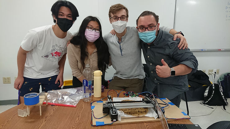
Fig. 1. From left to right: Justin Le, Darin Sumetanon, Matt Berger, Paul Ferrer.
Design:
Sketching:
The very first stage of this design was creating a preliminary sketch of the design. Before using CAD, it would be more efficient to jot ideas down on paper and come out with a rough visualization of the final product.

Fig. 2. Top, Side and Isometric Views of the 2.5 DOF System.
For clarity, the system would be on 80/20 rails (all mounted to a large wooden board), driven by stepper motors pulling cables along the length of the rails. This rail system controls 2 axes of movement. The "0.5" axis comes from the simple movement of the stamper, driven by a linear solenoid. With code we can manipulate the position of the stamper and actuate the solenoid when needed.
CAD:
The second stage of this design started with modeling in Solidworks. This allows us to view and manipulate everything efficiently. With CAD we can create an assembly, and create parts sized to fit perfectly to 8020, the stepper motors, and the linear solenoid (all while considering manufacturing / 3D Printing tolerances). Parts taken from GrabCAD included: Stepper Motor (NEMA17), Linear Solenoid.
To jump to the full Bill of Materials (BOM) click here.
8020.sldprt:
The first component to model was the 80/20 Aluminum Extrusions. GrabCAD had no pre-made .sldprt, so I created a simple 80/20 model in Solidworks, as realistic as possible. Measurements were made with calipers to create CAD somewhat true to size. Creating my own CAD for this part meant I could readily manipulate it, mainly for the purpose of extruding the part as desired.
The main purpose of this CAD was to be able to visualize the 80/20 in the complete assembly, it did not have to be truly exact.
These dimensions were in millimeters (mm).


Fig. 3. Cross Section of the modeled 80/20.
1/4" tapped hole in the center.
Fig. 4. 80/20 Isometric View.
FixedMotorMount.sldprt
This component was the first to be 3D printed was the Motor Hold, fixed at the end of an 80/20 extrusion. This part holds a motor at the end of a rail, meant to draw a cable and be able to pull a slider, in order to manipulate axes of the linear drive.

Fig. 5. FixedMotorMount.sldprt Isometric View.

Fig. 6. FixedMotorMount.sldprt Isometric View in assembly.

Fig. 7. FixedMotorMount.sldprt Top View in assembly and mates.

Fig. 8. Isometric View
Shown above is a top view of the Fixed Motor Hold. In Fig. 5 the blue ring in the center was measured to ensure that the cutout in the Motor Hold part would be able to sit flush with the top of the Stepper Motor. Fig. 6 shows a clearer view of the cutout and the flange.
Also in Fig. 5 outlined in blue is the mounting holes on the Stepper. These holes were manually drilled after the 3D Print, to ensure tolerancing during the printing phase did not misalign the holes. It was easier to drill manually than to try to assume the print would come out perfectly lined up to these holes on the Stepper model taken from GrabCAD - if nothing else it was for peace of mind.
Note: The cylindrical part mated to the motor shaft (bearing.sldprt), seen in Fig. 6, is a stand-in for the cable pulley. In real life, the cable and the pulley are both teethed so they do not slip. This part is seen frequently throughout the assembly.
FixedCableEnd.sldprt
This component was also fixed at the end of the 80/20, opposite the side of the Stepper Motor, meant to interface with the cable and allow the cable to pull the center slider (Fig. __). This part interfaced with the 80/20 by sliding into the top channel, and was also meant to be screwed into a 1/4" tapped hole at the end of the 80/20 (see Fig. 3.), hence the countersunk hole.
Note: The simple shaft through FixedCableEnd.sldprt, the simple bearing, and the 80/20, is a stand-in for a rod, meant to allow the bearing to spin freely (see Fig. 6. above).

Fig. 9. FixedCableEnd.sldprt Isometric View.

Fig. 10. FixedCableEnd.sldprt in assembly.
Riser.sldprt
This component was created as a way to normalize the height of the entire assembly, tall enough to raise the Stepper Motor off the ground. The design could have been perfected to be level with the motors, but with the uncertainty of the 3D print, it was safer to raise the motors off the ground. The risk was having the entire assembly tilt if the motors were too far below the spacers.
The flanges were meant to be able to secure the entire assembly to a wood board, to secure the whole assembly and ensure the 80/20 rails were parallel. Parallel rails were extremely important to ensure smooth movement of the axes. Holes were drilled after the printing phase.

Fig. 11. Riser.sldprt Isometric View.

Fig. 12. Four equally spaced Risers in assembly, circled in blue.
MovingMotorMount.sldprt
This component was meant to be anchored to the cable running between the motor and the bearing at the opposite end of the 80/20. Because the cable has teeth, it would rotate with the bearing fixed to the shaft of the motor. This concept turns angular displacement (of the motor) into linear displacement. The anchor part will move laterally in the channel of the 80/20. Shown below is proof of concept.

Fig. 13. Anchor extrusion Top View.

Fig. 14. Anchor extrusion Isometric View.

Fig. 15. PLA print with the cable.
This anchor concept is needed to drive the Moving Motor Mount. With a similar mount for the motor as in FixedMotorMount.sldprt, and an interface for 80/20, we get MovingMotorMount.sldprt.

Fig. 16. MotorMountMoving.sldprt Isometric View.

Fig. 17. MotorMountMoving.sldprt in assembly.
MovingCableEnd.sldprt
This component was built with the same concept as in MovingMotorMount.sldprt, except it needed to hold a shaft and bearing because it opposed a motor. These components together, with 80/20 between them, drive linear motion on the 2nd axis.

Fig. 18. MovingCableEnd.sldprt Isometric View.

Fig. 19. MovingCableEnd.sldprt in assembly.
SolenoidHolder.sldprt and CookieCutter.sldprt
SolenoidHolder.sldprt was built with the same cable-anchor concept, but it holds the solenoid, fitted with a stamper (CookieCutter.sldprt), meant to cut out cookies. The 0.5 axis comes from the movement of the solenoid stamping in the Y-Direction.

Fig. 20. SolenoidHolder.sldprt Isometric View.

Fig. 21. CookieCutter.sldprt Isometric View 1.

Fig. 22. CookieCutter.sldprt Isometric View 2.

Fig. 23. SolenoidHolder.sldprt and Cookie Cutter.sldprt in assembly.

Fig. 24. SolenoidHolder.sldprt and Cookie Cutter.sldprt in assembly, transparent to show solenoid.
LinearDriveAll.sldasm
With all the individual parts of the linear drive complete, CAD assembly can begin. This allows us to fully visualize the system in 3D before manufacturing and assembly.
Though not shown in the assembly, each linear drive has a cable strung from the motor shaft to the opposite end of the rail, which pulls the moving slider. This system drives the axes of motion.
Fig. 25. Full Assembly video showing X-Z axis movement (planar).
Code:
The program we used to manipulate the system was Repetir, which allowed us to send code to our Makerbase Board. Essentially, we give the motor an angular displacement and the phsyical pulley mechanism will translate that into linear displacement. With Repetir we created a simple sequence to move around and stamp. The most important consideration was syncing the two parallel rails, to create one axis of motion.
In Fig. 25 above, the first axis of motion is manipulated by the parallel linear drives, and the second axis of motion is manipulated by the linear drive running across. The "0.5" alludes to the simple stamper mechanism driven by the linear solenoidin the center.
See Assembly for videos of the assembled system in motion.
Manufacturing:
To begin the manufacturing stage, there needs to be a full account of all the parts needed to assemble the system, this means every CAD part and every non-CAD part including fasteners and pins, etc. etc.
Bill of Materials (BOM):

Note: The count for screws breaks down as follows:
4 for each Stepper Motor (x3)
2 for each Riser (x4)
1 for each Fixed Motor Hold (x2)
1 for each Fixed Cable End (x2)
Fig. 26. Full BOM.
3D Printing:
With most of these parts already in-hand, we just need to 3D Print each part that we've created in Solidworks. The first iterations of our prints were created with PLA. We found that because of the lower resolution PLA printer, these parts had tighter tolerances. For the sliders, it was more difficult to guarantee smooth movement so for some of our parts we opted for finer resolution SLA resin prints.

Fig. 27. FixedCableEnd and FixedMotorMount, both in PLA, slotting into the an 80/20 extrusion.

Fig. 28. MovingMotorMount in SLA. Note the cable slot with the teeth, is filled in; the resin print was messy and this part could not be recovered.
Fig. 29. Assorted prints and early stages of the final assembly. Shown in front is a broken CookieCutter.sldprt print.
There were a handful of considerations when designing for a print, and considerations for printing in general. Our design should be optimized for print tolerances. For example, the Moving parts with the teeth to anchor the cable, were estimated to the best of our ability. Printing the cable with exact measurements may yield a gap too small or large to fit the cable snug. Luckily, with our first iteration of the CAD, the print came out perfectly and the cable was fixed in the part.
Assembly:
With parts printed, all that was needed as to assemble the final product. The video below is a preliminary test of the linear drives. This was to ensure that before we proceeded to final assembly, the motors could be synced, and all the parts worked as expected.
Note the Fixed Motor Mounts did not have cutouts for the shaft of the motor yet. This video is proof of concept.
Preliminary Assembly:
Fig. 30. Preliminary assembly, showing proof of concept for converting angular displacement into linear displacement.
This early stage of the linear drives was not perfectly parallel, only "eyeballed". This test was mostly meant to see if the motors could drive the system. In the final iteration, it would be more important to ensure that the rails stay parallel to prevent unneeded friction between the slider and the inside of the rails.
Fig. 31. This assembly has all the correct components, and shows the linear solenoid "stamping".
Final Assembly:
The final assembly is shown below, mounted to a wooden board and stamping cookie dough during our ME360 Project Showcase.
_JPG.jpg)
_JPG.jpg)
Fig. 32. Two views of the final product during our showcase
Fig. 33. Final Assembly video 1.
Fig. 34. Final Assembly video 2.
Improvements:
Given more time and materials there were a handful of improvements that could have been made. With more careful manufacturing the whole structure could have been even more secure. In the end it was very stable, but there were some screws that wouldn't sit fully because either the hole was misaligned or the part came out poorly printed. In some ways this design felt somewhat makeshift, but it did work as expected, so that was all we needed.
One large consideration would be to find a way to stamp with more force. The linear solenoid seemed like it wasn't stamping all the way through the dough. In a realistic cookie cutting situation, you'd want the dough to fully separate from the cut, and shown in the videos, the dough doesn't seem fully cut (to the satisfaction of a hypothetical baker). This is also a function of having a thin enough cutter. With more time and careful planning, we could have created a mount for a store bought cookie cutter, for example.
One thing I did notice was that when the stamper was cutting, the reaction force acting back on the solenoid caused the rail to torque backwards. It wasn't enough to cause problems with movement, but enough that it seemed like the stamper wasn't stamping to its full potential. A quick solution to this would be to weigh the solenoid down to resist this reaction torque.
I could go on for days about improvements, but overall, this design worked well and my team and I are happy with the design and final result.
Takeaways:
Overall this project was a lot of fun but also taught me and my team a lot. It taught us about seeing design as not just CAD that can magically appear, but that we have to design with good manufacturing and assembly practice in mind. Being able to concisely lay out project goals is extremely important in how to get there; without clear goals, a path to the end product is more difficult.
Preparing this portfolio entry is a great exercise in being accountable for the design itself. It means I would have to understand the entire design process enough to explain to an audience in a concise way. Recounting my experiences with this design work is also helpful in that it makes me learn all the steps and solidfies my learning of these engineering concepts.
This project was also a great exercise in teamwork and communication. We were able to delegate work effectively and come out with a product that met its requirements in a timely manner.